IMU Digital Combo Board-6DOF ADXL345 and ITG3205: Difference between revisions
Jump to navigation
Jump to search
No edit summary |
|||
| (2 intermediate revisions by the same user not shown) | |||
| Line 26: | Line 26: | ||
SDA -> A4 | SDA -> A4 | ||
SCL -> A5 | SCL -> A5 | ||
More details about IMU 6DOF pleast visit [http://bildr.org/2012/03/stable-orientation-digital-imu-6dof-arduino/ Bildr Tutorial] | |||
==Example code== | ==Example code== | ||
[http://www.geeetech.com/Documents/6DOF%20example%20code.rar IMU 6 DOF Combo Board Example code] | [http://www.geeetech.com/Documents/6DOF%20example%20code.rar IMU 6 DOF Combo Board Example code] | ||
==How to buy== | ==How to buy== | ||
Click here to buy [http://www.geeetech.com/mu-digital-combo-board6dof-adxl345-and-itg3205-p-538.html IMU Digital Combo Board-6DOF ADXL345 and ITG3205] | Click here to buy [http://www.geeetech.com/mu-digital-combo-board6dof-adxl345-and-itg3205-p-538.html IMU Digital Combo Board-6DOF ADXL345 and ITG3205] | ||
Latest revision as of 07:09, 29 May 2012
Introduction
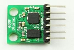
This product is a simple breakout for the ADXL345 accelerometer and the ITG-3205 gyro. You get a full 6 degrees of freedom With this board. The sensors communicate over I2C and one INT output pin from each sensor is broken out. If you need a simple and tiny board that gives you 6 degrees of freedom, this would be a good choice.
Features
- Tiny
- ADXL345 accelerometer
- ITG-3205 gyro
- 3.3V input
- 2C interface
Document
ADXL345 accelerometer datasheet
Usage
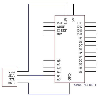
Here is a guide illustrates how to connect an IMU 6DOF board to Arduino. The following is a table describe which pins on the Arduino should be connected to the IMU 6DOF board.
VCC -> 3.3V
GND -> GND
SDA -> A4
SCL -> A5
More details about IMU 6DOF pleast visit Bildr Tutorial
Example code
IMU 6 DOF Combo Board Example code
How to buy
Click here to buy IMU Digital Combo Board-6DOF ADXL345 and ITG3205

